Chapter 7 Angle Measurement
7.1 Direction Information and Radar Coordinates
The previous chapters have obtained range, velocity, and detection results in the target list. Now one piece of information is missing: which direction is the target in?
What direction is it actually in?
A target is $50\,km$ from the radar with a velocity of $300\,m/s$. This is certainly useful information, but without knowing whether it's to the east or west, at low altitude or high altitude, command and early warning cannot translate into concrete actions. The same applies to weather radar. Saying "heavy rainfall $100\,km$ away" doesn't tell the reader which direction to look.
Angle measurement fills in the target direction. Range measurement captures time delay, velocity measurement tracks inter-pulse phase changes, detection checks if echoes cross a threshold; in angle measurement, the antenna's directivity becomes the protagonist. A radar can determine direction because its transmit and receive responses differ across directions. Beam scanning, angular resolution, angle measurement errors, and monopulse angle tracking all revolve around two questions: how to exploit antenna directivity, and which factors limit angle measurement results.
This content connects to threads from earlier chapters. Chapter 3 covered antenna directivity, Chapter 4 explained how "width limits resolution capability," and Chapter 5 discussed parameter estimation errors. Applied to the angular axis, these threads become three relationships: directions with stronger responses are more likely to indicate the target direction; the wider the beam, the easier it is for closely-spaced targets to merge; and noise, multipath, and pointing errors will bias angle estimates.
Why Direction Matters
Imagine standing on a playground. Someone says "there's a person $100\,m$ away, running toward you at $5\,m/s$." What would you ask? Most likely: from which direction? Straight ahead, from the side, or behind—the meaning is completely different.
Air defense radar works the same way. The radar detects three targets, all around $50\,km$ in range, velocities also near $300\,m/s$. Without direction information, these three targets could be in the same direction, or they could be coming from three different directions—east, south, and west. The first case requires concentrated handling; the second requires allocating resources in different directions. Identical range and velocity do not mean identical spatial positions.
Weather radar provides an easier example to understand. Strong echoes appear at $100\,km$ around the radar; with range alone, you can only say "there's heavy rainfall nearby." Adding azimuth allows you to say "heavy rainfall is approaching from the southeast." Those fan shapes, rings, and bright spots on radar displays are fundamentally combinations of range and direction.
Azimuth and Elevation
To describe a target's position in three-dimensional space, start with "which way to look." Standing at the radar position requires two actions: first rotate in the horizontal plane, then decide whether to look up or down.
Rotation in the horizontal plane is called azimuth, commonly denoted $\theta$. By convention, true north can be defined as $0^\circ$, rotating clockwise, with east at $90^\circ$, south at $180^\circ$, and west at $270^\circ$. The vertical angle is called elevation, commonly denoted $\phi$. The horizontal direction is $0^\circ$, upward angles are positive, downward angles are negative.
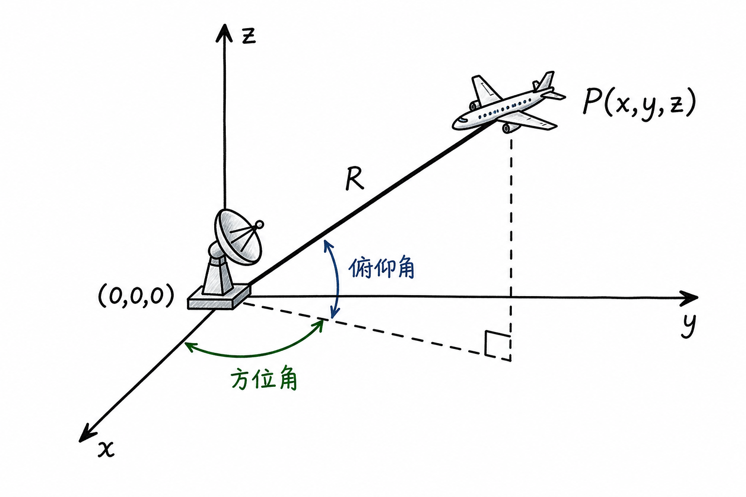
With azimuth, elevation, and range $R$, you can describe a target's position in the radar coordinate system. For example:
- A target due east, at horizontal level, range $10\,km$, can be recorded as azimuth $90^\circ$, elevation $0^\circ$, range $10\,km$.
- A target northeast, elevation $30^\circ$, range $20\,km$, can be recorded as azimuth $45^\circ$, elevation $30^\circ$, range $20\,km$.
- The target is directly overhead at a distance of $5\,km$, with an elevation angle of $90^\circ$. The azimuth angle loses practical meaning because all horizontal directions point to the same location.
This last case reminds us that coordinate representations also have boundaries. For ground-based search radars, targets exactly at zenith are uncommon; for ship-borne, airborne, or specialized tracking radars, near-zenith targets require more careful coordinate handling. Angle is not a single number—it typically includes at least azimuth and elevation.
Radar can measure angles because the antenna responds differently to different directions. Range measurement captures time delay, velocity measurement captures inter-pulse phase change; for angle measurement, the antenna's own directionality plays the primary role.
7.2 Antenna Pattern and Beamwidth
Main Lobe, Sidelobes, and 3 dB Beamwidth
A radar beam is not an infinitely thin line—it's more like a flashlight beam on a wall: brightest at the center, gradually dimming toward the edges, with no sharp "light/no-light" boundary in between. The antenna's transmission and reception of electromagnetic waves also follows this angular distribution.
Suppose the antenna points straight ahead. By measuring the radiated power or receiving sensitivity at different angles and plotting the results as a curve, we obtain theantenna pattern. The pattern describes the antenna's own directional response, not the target echo curve from any particular scan.
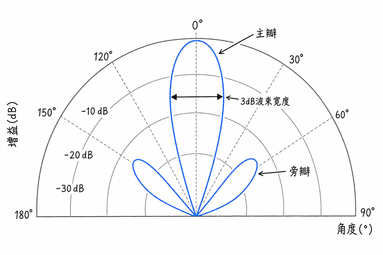
The highest peak in the center of the pattern is called themain lobe, which corresponds to the antenna's primary radiation or reception direction. The smaller peaks on either side of the main lobe are calledsidelobes. Sidelobe energy is lower than the main lobe, but never completely disappears. Strong targets appearing in sidelobe directions can still cause interference with angle measurement and detection.
The main lobe has a width. The common quantification method is the 3 dB beamwidth: The width between two angles where the power drops3 dB from the peak, i.e., to half the peak power. If a radar has a 3 dB beamwidth of $5^\circ$ and the antenna points at $0^\circ$, targets within approximately $-2.5^\circ$ to $+2.5^\circ$ remain in the main lobe's strong response region.
The antenna pattern is a curve showing how antenna response varies with angle; the echo intensity curve obtained during scanning angle measurement is the observed result of target echoes varying with beam direction. The former is a system property, the latter an observation result.
Wavelength, Antenna Size, and Beamwidth
Beamwidth is constrained by antenna size and operating wavelength. For introductory purposes, this approximate relationship can be used:
where $\theta_{\text{3dB}}$ is expressed in radians, $\lambda$ is the radar operating wavelength, $D$ is the effective antenna aperture, and $k$ is a coefficient related to antenna type and illumination method. Many rough estimates use $k\approx1$.
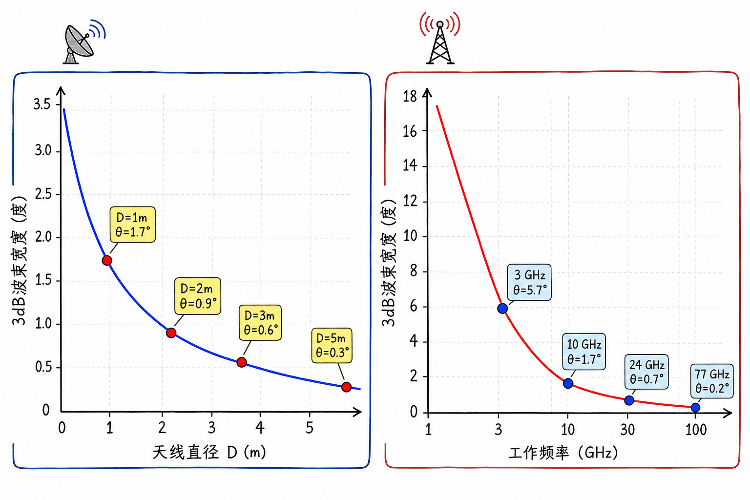
This formula shows: the larger the antenna, the narrower the beam; the shorter the wavelength, the narrower the beam. After calculating $\lambda/D$, multiply by $57.3^\circ$ to convert from radians to degrees.
Example 1: An automotive millimeter-wave radar operates at $77\,GHz$, with a wavelength of approximately
If the effective antenna aperture is $10\,cm=100\,mm$, then
Example 2: A weather radar operates at $3\,GHz$, with a wavelength of approximately $10\,cm$. If the antenna diameter is $3\,m$, then
Example 3: A search radar operates at $1\,GHz$, with a wavelength of approximately $30\,cm$. If the antenna aperture is $5\,m$, then
Narrow beams facilitate angle measurement and resolving closely-spaced targets, but they come at a cost. Larger antennas increase weight, cost, and installation space requirements; higher frequencies affect components, losses, and propagation conditions. Engineering systems typically do not pursue the narrowest possible beam, but instead balance search coverage, update rate, accuracy, cost, and platform size.
7.3 Angle Measurement via Beam Scanning
Mechanical Scanning
When the beam points at the target center, the echo is usually strongest. By scanning across different directions and recording echo intensity at each direction, the direction of the peak can be used as the target angle estimate. This is the principle of scanning angle measurement.
One scanning method involves physically rotating the antenna. Rotating radars commonly seen at airports, ports, and weather stations are examples of mechanical scanning. As the antenna rotates to each direction, it transmits pulses, receives echoes, and records range and intensity information for that direction.
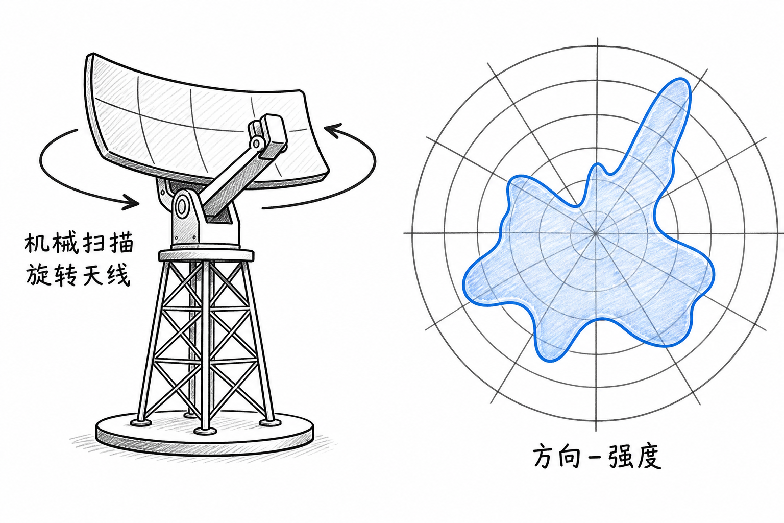
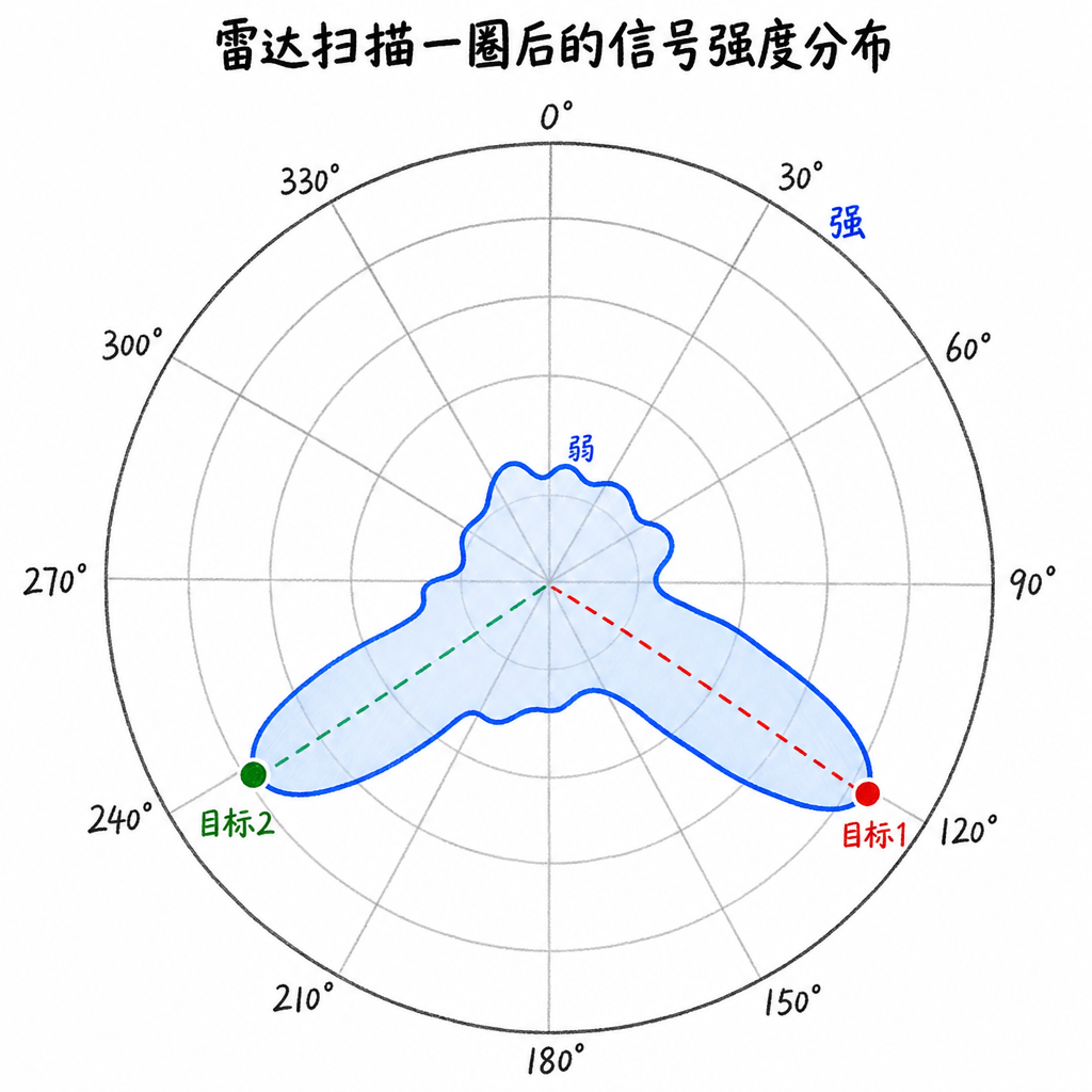
If the antenna starts at $0^\circ$ and records echo intensity every $1^\circ$, after completing a full rotation it produces a "direction-intensity" curve. Peaks in the curve at $120^\circ$ and $240^\circ$ indicate strong targets or echo regions in those directions.
Mechanical scanning is straightforward and reliable. The tradeoff is speed. Large antennas have mass and inertia and cannot be accelerated indefinitely. A search radar may take several seconds to complete one rotation; if a target maneuvers at high speed during these seconds, the angular information obtained by the radar becomes outdated. During mechanical scanning, the antenna spends most of its time looking in other directions, limiting the dwell time on any single target.
Engineering practice uses pragmatic solutions to mitigate this problem. For example, two radars can be installed back-to-back and rotated synchronously, looking in two directions separated by $180^\circ$ at the same time. This way, the entire system only needs to rotate half a revolution to achieve full azimuthal coverage, nearly halving the effective refresh time; the tradeoff is increased equipment count, installation space, synchronization, and calibration requirements.
The 'slowness' here is not just a matter of mechanical speed but also relates to the radar measurement itself. Each direction requires transmission, waiting for echoes, reception, and processing. Echoes from distant targets take time to return, and no matter how fast the scan, this waiting period cannot be eliminated.
Electronic Scanning
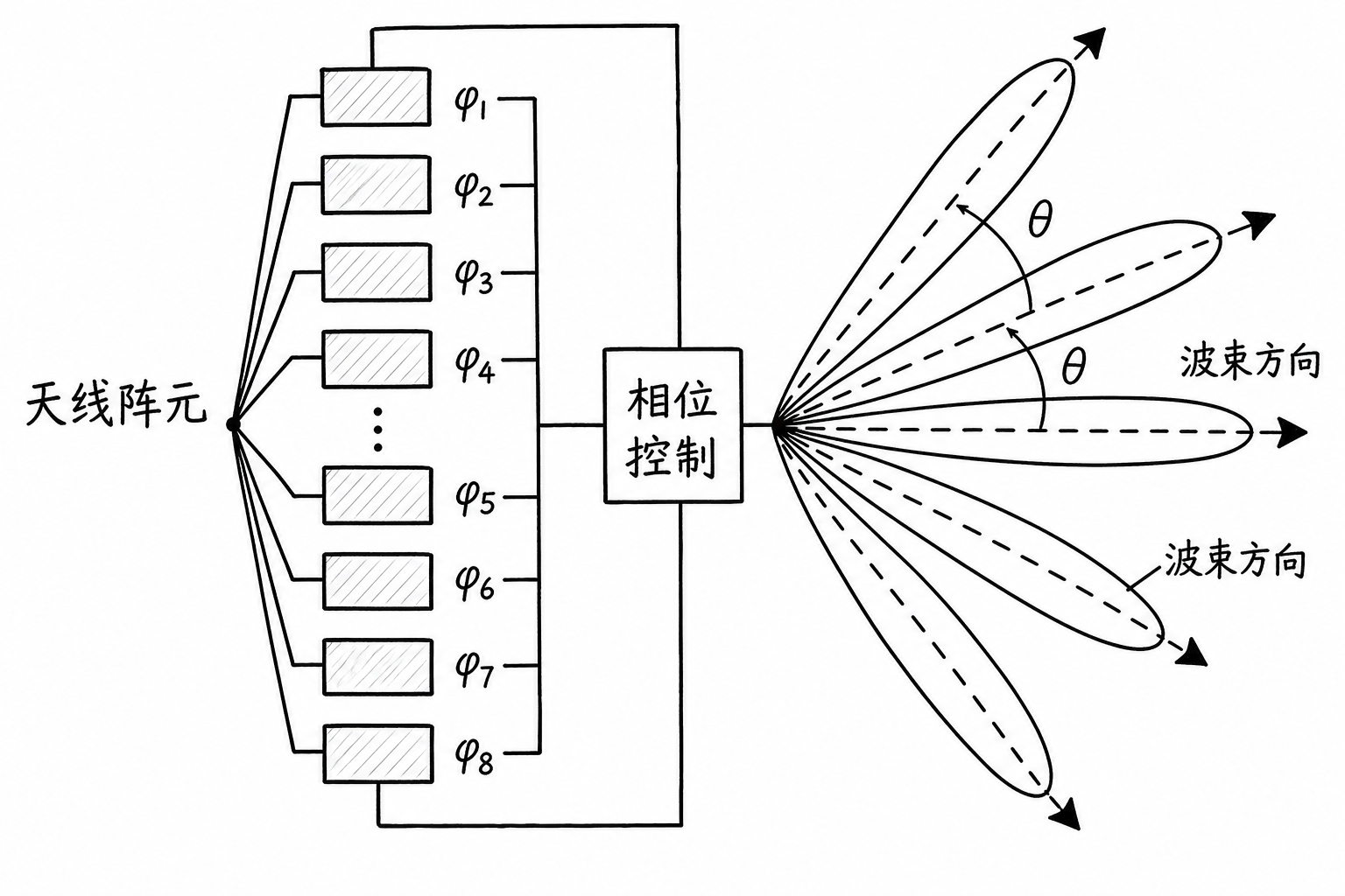
To steer the beam more rapidly, phased arrays change the mainlobe direction by adjusting the phase of each element in the antenna array. Electromagnetic waves from multiple antenna elements add constructively in one direction and destructively in others, causing the mainlobe to point in the desired direction. Changing the phase differences changes the mainlobe direction. This is the principle behind phased array electronic scanning.
The advantage of electronic scanning is beam agility. It does not require physically rotating a large antenna and can switch from one direction to another in a very short time, allowing more time to be allocated to approaching targets. Phased arrays are now very common in modern fighter radars, air defense radars, and large early warning radars.
Electronic scanning also has limitations. First, arrays are costly and power-hungry, with many elements requiring amplitude and phase control. Second, each direction still requires dwell time; one cannot simply 'point briefly' and obtain a reliable echo. Third, when the beam is steered too far from broadside, gain drops, sidelobes may rise, and beam shape degrades.
How phase differences precisely form beams and how digital beamforming estimates angle from array data belong to the domain of array signal processing.
7.4 Angular Resolution and Angle Measurement Accuracy
When Can Two Targets Be Resolved
In range measurement, if two targets' echoes are close together in time, only one peak may appear in the range profile. Angular measurement faces a similar problem: when two targets are too close in angle, can the beam resolve them as two targets? This capability is calledangular resolution。
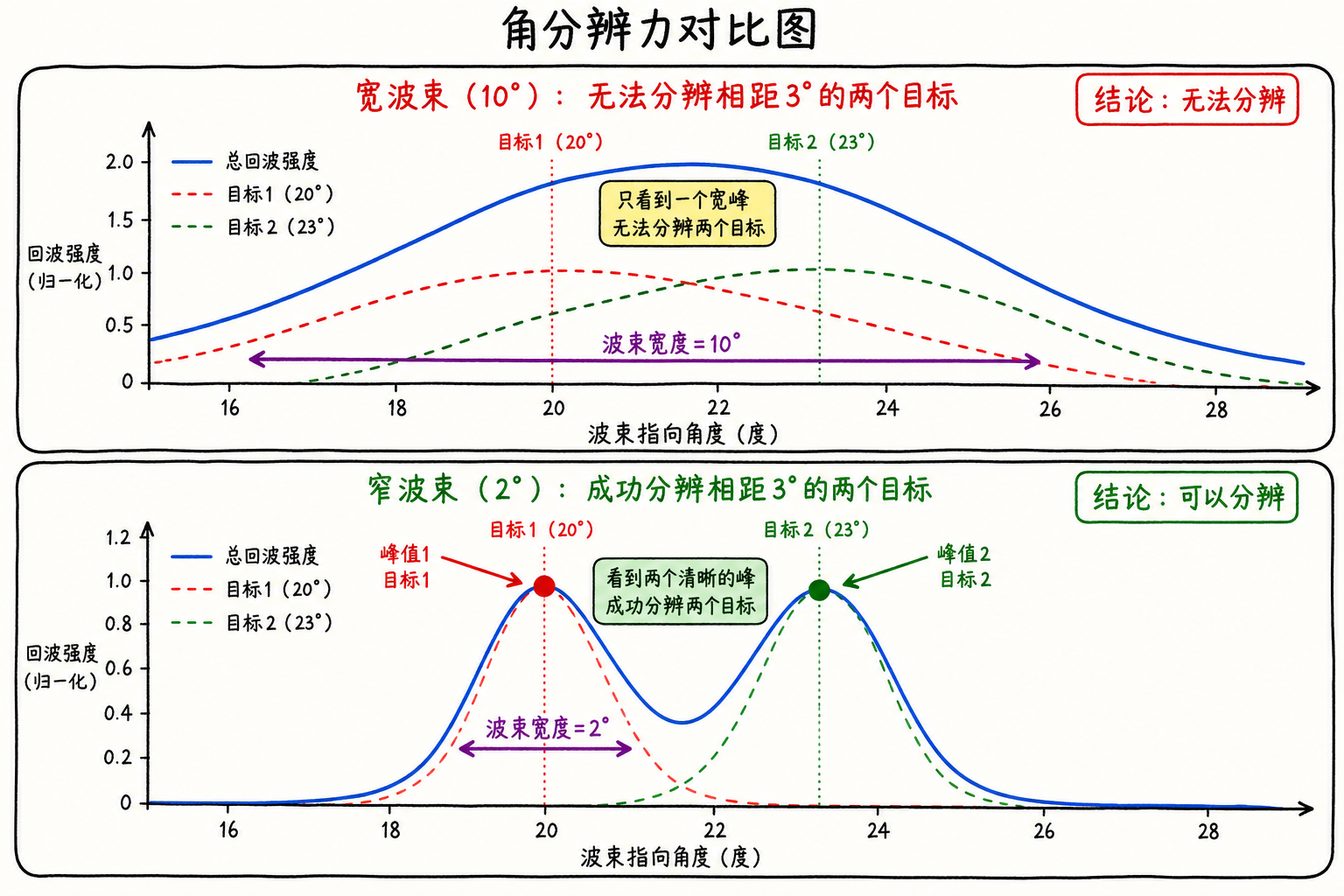
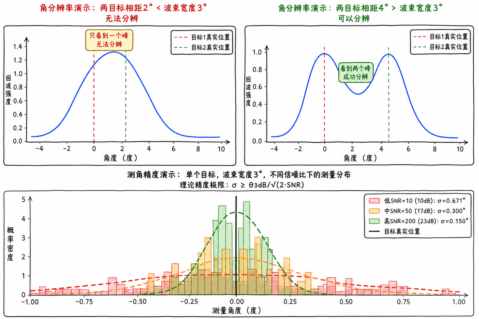
Suppose two targets are at the same range, one at $20^\circ$ and the other at $23^\circ$, with an angular separation of $3^\circ$. If the radar beamwidth is $10^\circ$, when the beam points near $20^\circ$ to $23^\circ$, both targets fall within the mainlobe, and the echoes easily merge into one broad peak, making it difficult for the radar to distinguish two targets.
If the beamwidth is only $2^\circ$, the situation differs. When the beam points to $20^\circ$, it primarily illuminates the first target; when it turns to $23^\circ$, it primarily illuminates the second target. Two peaks appear more easily in the scan curve, making the two targets easier to separate.
In engineering estimates, angular resolution can be considered on the same order as the 3 dB beamwidth:
This is a common engineering rule of thumb, not a strict theorem. Two targets at the same range with similar strength are easier to separate when their angular difference exceeds the beamwidth; when the angular difference is smaller than the beamwidth, the echo peaks tend to merge.
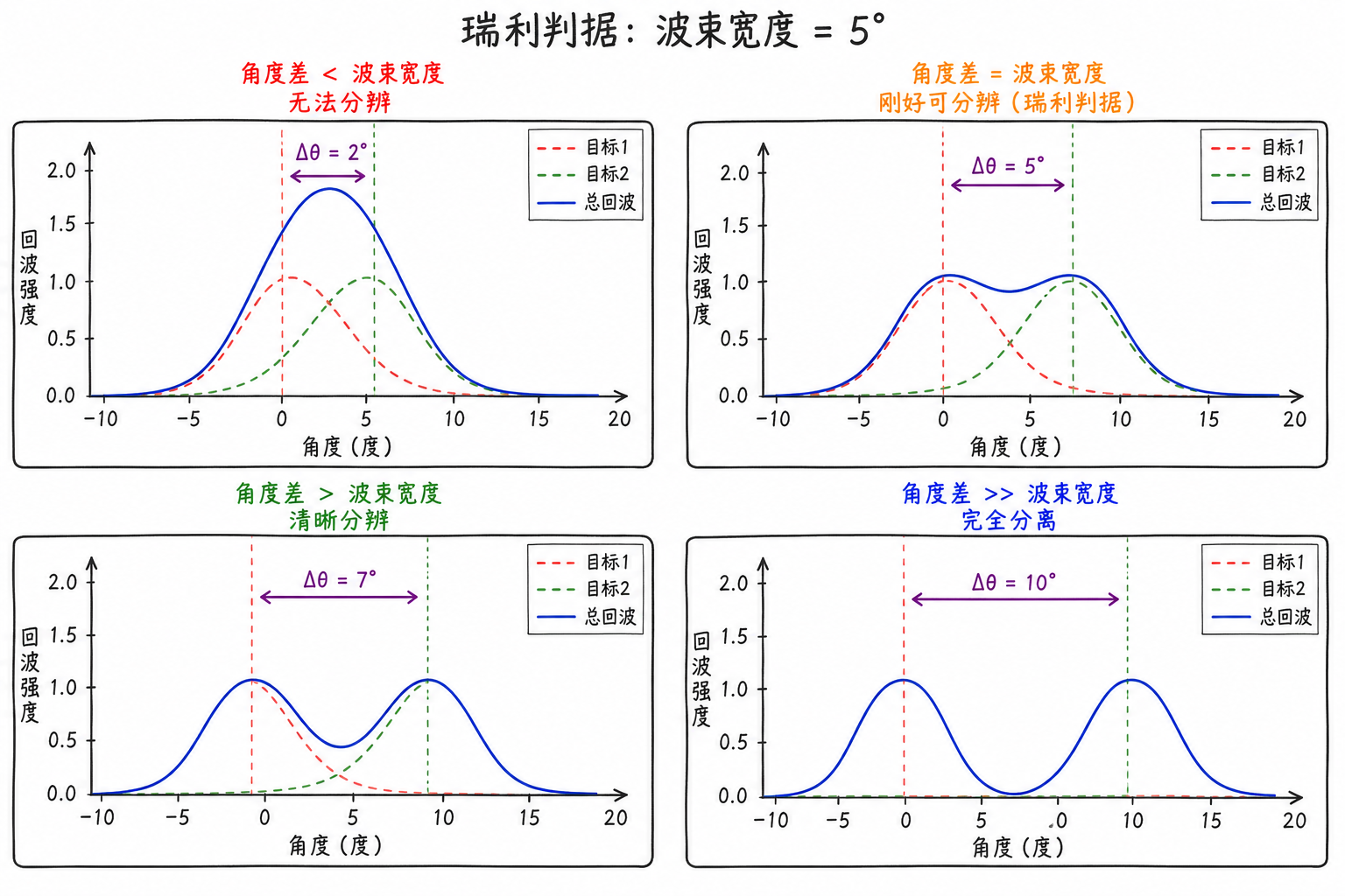
The Rayleigh criterion uses the mainlobe peak of one target and the mainlobe null of another target to determine resolvability. The narrower the mainlobe, the easier it is to separate adjacent targets in angle.
Angular resolution can also be understood in terms of cross-range distance. If the target range is $R$ and the angular difference between two targets is $\Delta\theta$ (in radians), their cross-range separation is approximately
For the same $2^\circ$ angular difference, the farther from the radar, the larger the corresponding cross-range distance. Therefore, many radar specifications provide both angular resolution and operating range.
Distinction Between Resolution and Accuracy
Angular resolution is easily confused with angle measurement accuracy. Both relate to "how accurate the angle is," but they address different questions.
Angular resolution asks: can two targets be separated? Angle measurement accuracy asks: how precisely can a single target's angle be estimated?
Using the previous example: two targets at $20^\circ$ and $23^\circ$ with a beamwidth of $10^\circ$ may not be resolved as two peaks by the radar—this is insufficient angular resolution. However, if there is only one target at $30^\circ$, the radar can estimate the angle to around $29.8^\circ$ or $30.2^\circ$ through the echo curve peak, multi-pulse averaging, and refined estimation algorithms. Single-target estimation can be finer than the beamwidth, but this does not mean two closely spaced targets can necessarily be separated.
| Concept | Question Asked | Primary Limitation | Typical Understanding |
|---|---|---|---|
| Beamwidth | How wide is the antenna mainlobe | Wavelength, antenna size, illumination method | Antenna intrinsic properties |
| angular resolution | Can two targets be separated | Beamwidth, target strength, processing method | Two-target problem |
| Angle measurement accuracy | How large is the angle estimation error for a single target | Beamwidth, SNR, algorithm, calibration | Single-target problem |
Angle measurement accuracy is commonly described by standard deviation $\sigma_\theta$. An order-of-magnitude relationship is:
The narrower the beam, the more sensitive the echo is to angular changes; the higher the SNR, the more stable the peak or ratio. This expression only shows the trend; specific coefficients depend on beam shape, angle measurement method, target fluctuation, and processing algorithm.
For example, with a beamwidth of $3^\circ$ and SNR of $100$ ($20\,dB$), the random angle measurement error may be on the order of a few tenths of a degree. Real systems are also affected by multipath, angle scintillation, and antenna pointing errors, so engineering specifications typically cannot rely solely on theoretical estimates under thermal noise.
7.5 Main Sources of Angle Measurement Error
Noise
There is always noise in the receiver. Noise superimposed on the echo causes the scan curve or monopulse ratio to jitter. If the true target direction is $30^\circ$, ideally the peak should be at $30^\circ$; with noise added, the peak may appear at $29.8^\circ$, $30.1^\circ$, or $30.3^\circ$.
The lower the SNR, the greater the jitter. The wider the beam, the flatter the curve near the peak, and the same noise is more likely to push the estimated position off. Reducing beamwidth, increasing transmit power, adding coherent integration, or averaging multiple measurements can all reduce random errors caused by noise.
The random error here does not always "deviate in a fixed direction." In multiple measurements, it may shift left at one time and right at another. In engineering, standard deviation is commonly used to describe this jitter range.
Multipath Effects
Multipath is a troublesome error source in low-elevation angle measurement. Electromagnetic waves can illuminate the target directly, or hit the ground or sea surface first and then reflect to the target; echoes returning to the radar may also travel multiple paths. Two paths, two echoes, with different times and phases.
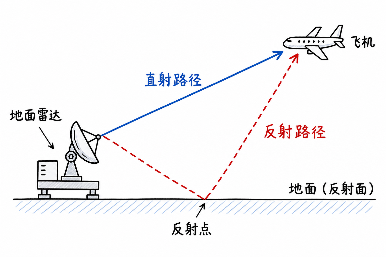
When two echoes superimpose, the equivalent echo seen by the radar may appear to come from another angle, causing the angle measurement to deviate. This deviation does not necessarily manifest as random jitter; sometimes it remains consistently high or low for a period of time.
For example, an aircraft at altitude $300\,m$ and horizontal distance $10\,km$ has a true elevation angle of approximately
The ground reflection path can be roughly viewed as a "mirror target" $300\,m$ underground, corresponding to an elevation angle of approximately $-1.7^\circ$. When the direct echo and reflected echo superimpose, the equivalent elevation angle may deviate from the true value, with the deviation magnitude depending on the reflection intensity and phase relationship.
Sea surface reflection is even more unstable. Sea surface fluctuations change the reflection path, and when shipborne or shore-based radars track low-altitude targets, angle measurements may fluctuate over time. Increasing antenna installation height, using narrower beams, selecting appropriate polarization and frequency, and suppressing multipath in signal processing can only mitigate the effects, rarely eliminating them completely.
Angular Glint
Many previous examples treat the target as a point target. Real aircraft, ships, or missiles consist of multiple scattering centers such as the nose, wings, tail, engine compartment, etc. The echo strength from different scattering centers varies with attitude changes, and the equivalent scattering center seen by the radar also moves.
When shining a flashlight on a keychain and rotating the keys, the brightest reflection point jumps between different keys and edges. Radar viewing complex targets is similar: at one instant the nose reflects strongly, at the next instant the wings reflect strongly, and the equivalent "bright spot" position changes. This angle measurement jitter caused by changes in the target's scattering centers is calledAngular Glint(angular glint)。
Angle glint significantly affects precision tracking. It originates from the target's own scattering structure, and simply increasing receiver sensitivity cannot eliminate it. Multiple frequencies, multiple viewing angles, wideband signals, and temporal smoothing can alleviate it, but cannot turn a complex target back into a point target.
Pointing Error and Calibration
The angles provided by radar also depend on the antenna "knowing where it points." Mechanical scanning radars have motors, gears, bearings, and turntables; installation errors, gear backlash, wind loading, and temperature changes can all cause the actual pointing to deviate from the reading. Although phased arrays lack large mechanical rotation, the amplitude, phase, and position of each element cannot be perfectly ideal, causing beam pointing deviations.
These types of errors are usually reduced through calibration. Radars can observe beacons, satellites, or ground targets at known positions, compare measured angles with true angles, and then correct the pointing model. For high-precision systems, calibration itself is part of the angle measurement capability.
| Error Source | Main Manifestation | Common Mitigation Methods |
|---|---|---|
| Noise | Random jitter in angle measurements | Increase SNR, multiple averaging, narrow beam |
| Multipath | Low-elevation target deviation or fluctuation | Increase antenna height, suppress reflection paths, select polarization and frequency |
| Angular Glint | Complex target equivalent scattering center glint | Wideband, multi-frequency, multi-aspect, temporal smoothing |
| Pointing error | Overall angular measurement bias | Installation calibration, phase calibration, periodic calibration |
Actual angle measurement results are often a combination of multiple error sources. Low-altitude targets may be primarily affected by multipath; high-SNR long-range targets may be mainly limited by pointing calibration; maneuvering targets may exhibit strong angle glint. When diagnosing error sources, one cannot rely on a single theoretical formula alone.
7.6 Monopulse Angle Measurement
Sum Channel and Difference Channel
Scanning angle measurement relies on "probing": the beam points in one direction to measure echo intensity once; then switches to another direction and measures again; finally comparing which direction yields the strongest signal. For fast-moving targets or precision tracking, this direction-by-direction comparison becomes too slow.
Monopulse angle measurement simultaneously obtains two types of information from a single echo: "how strong is the target" and "how far is the target from the center." The most common approach is to form asum channel $\Sigma$ and adifference channel $\Delta$。
First, view it as two receiving sub-apertures, left and right. When the target is at the beam center, both sides receive signals of equal strength; when the target is to the left, the left side receives a stronger signal; when the target is to the right, the right side receives a stronger signal.
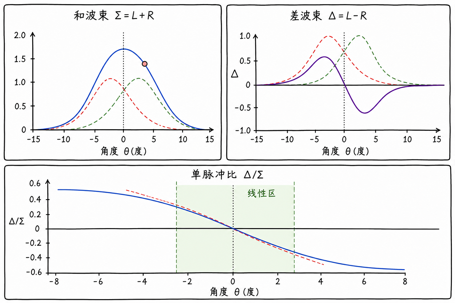
Adding the signals from both sides yields the sum channel $\Sigma$. Like a conventional beam, it represents the total target echo strength and can be used with range and velocity processing. Subtracting the left and right signals yields the difference channel $\Delta$. The difference channel is zero near the center, positive when the target deviates to one side, and negative when it deviates to the other.
A numerical example makes this clearer. If the target is at the center, both left and right channels receive $1\,V$:
If the target is to the left, the left channel is $1.2\,V$ and the right channel is $0.8\,V$:
The difference channel indicates the direction of deviation, and the magnitude of the difference indicates the degree of deviation. In this way, the radar can estimate the target's deviation direction from the center in a single echo, without waiting for the beam to complete a full rotation.
Ratio and Angle Estimation
If we only look at $\Delta$, we encounter a problem: the target's own strength also affects the difference value. Distant targets, weak RCS targets, and nearby targets, strong RCS targets may have different echo amplitudes even with the same angular deviation. Using only the difference to estimate angle would confuse 'weak target' with 'small deviation'.
Therefore, monopulse typically uses a normalized ratio:
In the previous example, when the target is to the left
If the overall echo from a target at the same angle becomes half as strong, with the left and right channels becoming $0.6\,V$ and $0.4\,V$, then
The ratio remains constant. It removes the target's overall strength, leaving information that better reflects angular deviation.
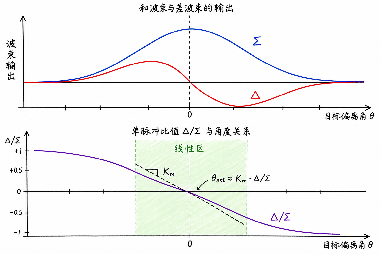
Near the beam center, the monopulse ratio and target deviation angle often have an approximately linear relationship:
where $K_m$ is a coefficient determined by the antenna beam shape and calibration results. Practical systems typically obtain this curve through calibration; the formula on paper only provides an approximate relationship.
The advantage of monopulse angle measurement is speed, and it is also better suited for tracking. The cost is more complex hardware and channels: the system needs to simultaneously form sum and difference channels, and maintain consistent amplitude and phase across all channels. If the channels are imbalanced, $\Delta/\Sigma$ itself will introduce errors.
Full amplitude comparison, phase comparison, multidimensional monopulse, and array processing belong to advanced topics in radar measurement and array signal processing.
7.7 Exercises
Exercise 1: Beamwidth and Angular Range
A search radar has a 3 dB beamwidth of $5^\circ$. During one scan, the radar detects a strong echo at azimuth $30^\circ$. What angular range might the target roughly fall within?
Solution: For a rough estimate, the strong region of the main lobe can be considered approximately $30^\circ\pm2.5^\circ$, that is, $27.5^\circ$ to $32.5^\circ$. This is only a range estimate, not a precise angle measurement result; the specific target angle also depends on the echo curve shape, SNR, and angle measurement method.
Exercise 2: Angular Resolution Assessment
A radar has a beamwidth of $8^\circ$. There are now two targets at the same range, one at $20^\circ$ and the other at $23^\circ$. Can this radar easily resolve these two targets?
Solution: The angular separation between the two targets is
$3^\circ$, which is less than $8^\circ$. By a basic estimate, they are likely to fall within the same main lobe response, potentially merging into a single broad peak on the scan curve, making it difficult to separate them into two independent targets.
Exercise 3: Estimating Beamwidth
A radar operates at $10\,GHz$ with an antenna diameter of $2\,m$. Taking $k\approx1$, estimate the 3 dB beamwidth.
Solution: First calculate the wavelength:
Then use the approximate relationship:
Convert to degrees:
Therefore, this radar's beamwidth is approximately $0.86^\circ$.
Exercise 4: Multipath Effect Identification
A shipborne radar is tracking a low-altitude aircraft. Based on the aircraft's altitude and range, the true elevation angle should be approximately $10^\circ$, but the radar-measured elevation angle often fluctuates around $8^\circ$ to $9^\circ$. What is the most likely cause?
A. Receiver thermal noise B. Multipath effect caused by sea surface reflection C. Insufficient target range resolution D. PRF setting too low
Solution: Most likely B. Low-altitude targets and the sea surface easily form a reflection path, and the superposition of direct and reflected echoes changes the equivalent angle of arrival. Noise typically manifests as more random jitter; range resolution and PRF primarily affect range and velocity-related issues, which are not the main concern here.
Exercise 5: Difference Between Resolution and Accuracy
Determine whether the following statement is correct and explain why.
- Good angular resolution means two targets at similar angles are easier to separate.
- Good angular accuracy means the angle estimation error for a single target is smaller.
- If a radar beamwidth is $5^\circ$, it absolutely cannot estimate a single target's angle to within $1^\circ$.
- If single-target angular accuracy reaches $0.5^\circ$, it can definitely separate two targets spaced $0.5^\circ$ apart.
Explanation: 1 and 2 are correct. 3 is not necessarily correct—single-target estimation can be finer than the beamwidth. 4 is incorrect—whether two targets can be separated depends mainly on angular resolution and echo shape, not single-target angular accuracy.
Exercise 6: Scanning Angle Measurement vs. Monopulse Angle Measurement
Determine whether the following statements are correct.
- Sequential lobing typically requires comparing echo intensities across multiple beam directions.
- Monopulse angle tracking can estimate the angle offset using sum and difference channels from a single echo.
- Monopulse angle tracking requires no calibration whatsoever.
- Electronic scanning has no time constraint for waiting for echoes.
Explanation: 1 and 2 are correct. 3 is wrong—monopulse ratios and channel consistency both require calibration. 4 is wrong—beam switching can be fast, but each direction still requires transmission, waiting for echoes, and data processing.
Exercise 7 (Optional): Beam Scanning Angle Measurement Experiment
If the supporting MATLAB files are available, you can run ch07_beam_scanning_demo.mto observe the relationship between scanning angle and echo power curves. Focus on three things: whether the peak appears near the target angle, whether two peaks merge when two targets are close together, and how the curve changes when the beamwidth narrows.
Exercise 8 (Optional): Monopulse Ratio Experiment
Run ch07_monopulse_demo.mto observe the sum beam, difference beam, and $\Delta/\Sigma$ curves. Focus on how the difference channel sign changes when the target is to the left or right of center; and whether $\Delta/\Sigma$ is more stable than $\Delta$ alone when the overall echo strength varies.